Increase productivity and accuracy of your engineering office through easy rule based CAD and BOM Automation
FormulaCAD is a unique CAD automation solution designed to provide enormous power, ease and collaboration.
FormulaCAD automates the creation of drawings and modules by defining reusable unit components stored inside a database and controlled through user-defined rules.
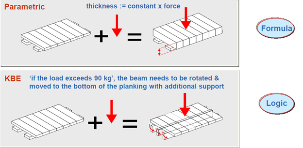
Standard CAD software have parametric facilities, whereby change in parameter will lead to change in dimension of geometry or model. However, Knowledge based Engineering or Rules based Automation goes much beyond that, whereby it becomes possible to capture and implement much more complex rules and logic, like the one shown in above figure.
FormulaCAD leads to following benefits:
Increased productivity
Faster Design and Timely Delivery
Capture of design rules and knowhow
Consistency
De-skilling of routine job
FormulaCAD Architecture
Rules Driven Creation of CAD Models – assembly / drawing
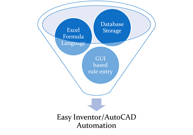
Replaces Programming paradigm with
* Database
* Familiar Formula Language
* Front end GUI
FormulaCAD Rule Definition
Excel - like Formula Language
Familiar Excel functions like for Engineering, information, logical, lookup, math, date and time, text and data
Customized for use in CAD environment
* Point functions
* Vector functions
Can be customized by Risersoft to provide more functions as per project requirement
Easy-to-use Graphical User Interface
Familiar and easily navigable user interface for rule definition and execution
Formula Builder feature with syntax highlighting and test formula facility
Standalone apps with no dependency on Visual Studio or other development environments.
Rule Types Overview
Parameter
* Define a parameter and its formula
Child
* Call other components into a parent component
* Enables working in context of unit components in a “building block” approach.
Snapshot
* Drawing complete with title block, borders and field values
* Word documents with pictures and text from the CAD model
BOM
* Bill-Of-Material Rule can be used to generate detailed BOM along with geometry
Inheritance
* Define parameters and actions once and re-use as required
Easy-to-use Graphical User Interface
Familiar and easily navigable user interface for rule definition and execution
Formula Builder feature with syntax highlighting and test formula facility
Standalone apps with no dependency on Visual Studio or other development environments.
Cloud Database Backend
FormulaCAD stores its data in a database leading to various advantages:
Listings and Reports.
* Salient Example: Where-used reports of parameter rule
Data Tools like Design Tables for
* Engineering Data Management
* Table based components for managing a family of similar parts / assemblies.
Team Collaboration
Integration with ERP / Design systems
FormulaCAD 2D
Define and execute 2D rules
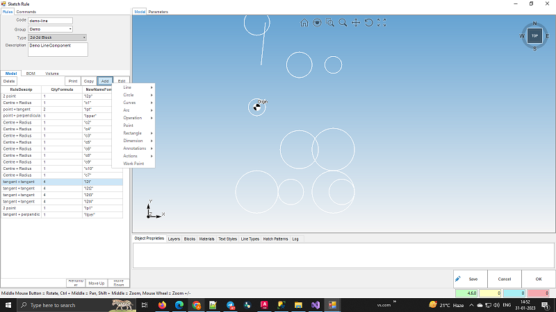
FormulaCAD has a full featured user interface for 2D rule definition that can be used to define rules and execute them either in test mode or for a particular customer work order.
Define Rules
Base Entities
FormulaCAD defines all AutoCAD entities as base components that can be called in any parent component
Most 2D Entities are available
* 2D Curves
* Line, Polyline, Rectangle, etc
* Circle, Ellipse, Arc, etc
* Annotations
* Text, Multiline Text
* Leader, TextLeader
* Arrays
* Rectangular
* Polar
Entity definition
* Each entity has multiple ways of definition
* For example, Rectangle can be defined using point + length + width or point1 + point2
* Multiple entity definition feature resembles the facility provided by Autodesk user interface
Existing Blocks
* Existing blocks can be associated with a FormulaCAD component and called by geometry creation rules.
Geometry Manipulation Actions
FormulaCAD allows rule definition for manipulation of entities just as you would do it through the 2D user interface.
Following actions are available:
Move
* Move entities from one point to another
Mirror
* Mirror entities with reference to a mirror line and keep or delete the source entities
Trim
* Trim entities on the intersection points
Rotate
* Rotate entities with reference to a base point and a rotation angle
Geometry Query Functions
FormulaCAD formula language has special functions for querying the geometry model and using the data for defining further rules.
Execute Rules
Create 2D geometry and BOM
Each component definition results into an 2D block
Nested components will result into nested 2D blocks
Create geometry on the fly with “Test component” feature – FormulaCAD will instantaneously create geometry in the 2D window as per defined rules
Any BOM rules are also evaluated and BOM generated.
Examine the FormulaCAD run log
Each run generated a run log which is detailed output of what parameters were calculated and what values were obtained
Any error information and suggestions are also output leading to rich iterative workflow.
FormulaCAD for 3D
Define and execute FormulaCAD rules from within CAD environment
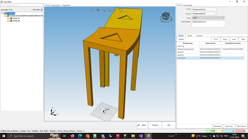
FormulaCAD has a full featured user interface for 3D rule definition that can be used to define rules and execute them either in test mode or for a particular customer work order.
Define Rules
Base Components
Part authoring with sketch constraints
Part authoring with 3D Entities like Box, Cone, Cylinder, Sphere
Map model parameters to component local parameters
Entity Marker
* Select faces and edges in Inventor model and give it a user-defined name
* Use this name while defining constraint rules
Call any of the base component in a parent component with a variable quantity defined in terms of parameters
Geometry Manipulation Actions
FormulaCAD allows rule definition for manipulation of entities just as you would do it through the 3D user interface.
Following actions are available:
3D Boolean
* Union, Subtraction
Oppose/Align
* Mate or Flush two entities with an offset distance
Move
* Move entities from one point to another
Mirror
* Mirror entities with reference to a mirror line and keep or delete the source entities
Rotate
* Rotate entities with reference to a base point and a rotation angle
Execute Rules
Create 3D Assemblies on the fly
Each component definition results into an 3D Assembly
Nested components will result into 3D Assembly Tree
Create assembly on the fly with “Test component” feature – FormulaCAD will instantaneously create assembly in the 3D window as per defined rules
Examine the FormulaCAD run log
Each run generated a run log which is detailed output of what parameters were calculated and what values were obtained
Any error information and suggestions are also output leading to rich iterative workflow.
Cloud based Workflows
Web Application
Login from a standard web browser
Change parameters and execute components
View resultant geometry from within the browser
Web Services
FormulaCAD Web API for Parametric CAD generation from within your web apps
Need to pass parameter values and get geometry back as per defined rules