Generate control schematic reports easily even when working with vanilla CAD software.
Prepare
Inventory Item codes, Device List, Terminal types and numbers, Mounting information, Lug Types, wire bus list and assignment.
Report
Terminal Block Diagram Wiring Diagram Material List Labels, Hardware and Lugs Interconnection List
Vanilla CAD
Automate control schematic reports even when working with vanilla CAD software.
Features
Generate control schematic reports easily even when working with vanilla CAD software.
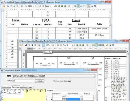
VisualCircuit allows you to generate control schematic reports:
Material List integrated with Inventory Item Codes
Terminal Block Diagram
Wiring Diagram
Panel Interconnections
Labels, Hardware and Lugs
Usual scenario can be described as follows:
40-45% of the time is spent in the preparation of electrical schematic and the remaining time is spent in the “rest” of the drawings.
Manual preparation of follow-on drawings leads to repetition of work and chances of error.
Traditional Industry approach has been to provide electrical schematic software which is used to draw the scheme and then generate other drawings
Generally, this increases the time and skill required to operate the software
Further, the Electrical CAD software tends to be expensive and existing “vanilla” CAD software need to be replaced.
Visual Circuit proposes an alternate workflow:
Allows use of existing CAD software for schematics
Provides tools to automate the rest of the documents
Provides graphical user interface for entry of devices and their wire buses and generates several follow through documents eliminating manual work.
Works in conjunction with your existing CAD software and NOT as a replacement.
Scheme Preparation
Inventory Item codes and Device List
Define Coding system to indicate significance of various digits in a code
Define unique Item code for each unique orderable item
Define BOM for each item. For example, a contactor assy may contain a base contactor and an add-on block.
Define control schematic specific information for each item:
* Terminal Block Diagram
* Add a collection of terminal sets
* Choose type for each terminal set, such as NO contact, NC contact, Coil etc.
* Define terminal nos. for each terminal set
* Mounting information
* Required to generate mounting hardware list
* Lug Types
* Required to generate lug list according to bus wire size selected in scheme
Mounting Guide
Each control device has usually got two mountings: indoor mounted and panel mounted.
Maintain standard mounting codes with RTF document for mounting info
Maintain hardware required for each mounting code.
One mounting code can be assigned to multiple devices.
Terminal Sets
Define standard terminal sets
Example: NO contact, NC contact, Coil, Selector Switch 3 Way etc.
Define no. of terminals in the terminal set. Devices which use this terminal set will have to define terminal nos. accordingly.
Assign a representative image for the terminal set:
* The graphical wiring diagram will be generated using this image.
* Position the terminal no. and wire no. position on the image using the Graphical designer.
Prepare Scheme
Scheme is prepared per work order.
Enter control panels and their types such as indoor, outdoor or field area
Enter devices located in each panel:
* Choose from the master device list
* Assign wire nos. to each terminal as defined in the device
* Device wiring diagram is generated on the fly
* Define labels used for the device
Maintain wire buses for the scheme
* Define size and colour
* Assign device terminals to the wire bus
Outputs
Printable Reports
Terminal Block Diagram
* Panel wise
Wiring Diagram
* Graphical figures according to the images assigned in the device masters
* Panel wise
Material List
* Includes Device BOM
* Panel Wise
Labels, Hardware and Lugs
* Labels are as entered during scheme preparation
* Hardware are generated from the mounting code assignment
* Lugs are calculated from the lug type assignment and wire bus size assigned
* Panel wise or work order wise
Interconnection List
* Each unique panel combination is generated separately
* Cables are calculated according to device rules defined and assigned separate identifiable codes
* Includes no. of cores for each cable and connected device terminal nos.